
In part 3 of the CloudBurst blog series, I will discuss the logical architecture of the appliance and a basic physical topology demonstrating a practical scenario. In part 2, I mentioned that the CloudBurst device is modular and actually consists of multiple hardware and software components. Let’s start with the high level logical architecture of the appliance – refer to figure 1.0 below. The end users (cloud users or administrators) interact with a browser-based interface to either request virtual resources or manage the cloud.
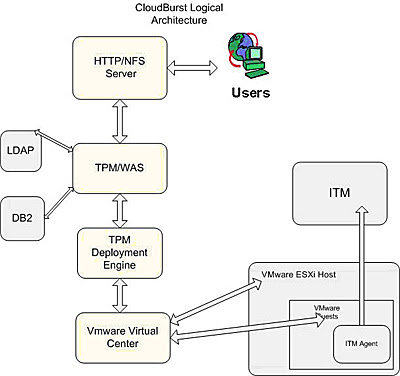
Figure 1.0 – Logical Architecture
A quick glance at the logical architecture reveals that the key components come from the Tivoli, WebSphere and VMware stacks. The first block in the overall stack is the IBM HTTP Server which handles the user requests. The HTTP Server forwards the user requests to the Tivoli Provisioning Manager and the WebSphere software stack, which form the heart of the overall architecture and run the IBM cloud-computing software. The HTTP Server requests are handled by the TPM and the stack of Cloud computing software that is running on the WebSphere Application Server. The Tivoli Provisioning Manager makes use of the pre-built automation workflows and set of scripts which actually drive the self-service model which serves the VMs requested by the end user. The Cloud computing software also handles any errors and exceptions. The data of the TPM and the WAS Cloud computing software (blue code) is stored in the DB2, while user info is stored in the LDAP. The TPM deployment engine acts as a broker and fulfills the end user requests. Its running set of automation packages and scripts.
The TPM deployment engine makes automation and web service calls to the VMware virtual center. The VM VC manages all the hypervisors and virtual machines which are running on base hardware. The VM VC interacts with physical machines. The physical machine is running a hypervisor – a light-weight process that runs the actual VMs which the end users will be accessing. The VC also provisions and performs customization on VMs.
ITM provides monitoring of the VMs and a dashboard for Cloud Admins to monitor the VMs and the VMware stack.
Let’s now consider a physical topology demonstrating a practical usage of the CloudBurst device. Figure 2.0 below illustrates how different users interact with the ‘Cloud’ to request resources. The ‘Resource Cloud’ is an abstraction representing the CloudBurst appliance, which can be used to create a private cloud. The resources in this case are VMware images which are provided by the customer and cataloged and stored in the image repository. A typical example would be developers working on WebSphere Portal development requiring VMware images which provide a rational development environment along with a Portal Server test instance.
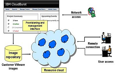
Figure 2.0 – Logical View/Scenario
The figure also illustrates the CloudBurst browser-based interface, which provides provisioning and management of the Cloud Resources. There are two basic categories of users: end users (software developers and quality assurance engineers) and administrators. The Resource Cloud provides a self-servicing platform for end users to request and use resources. The administrators use the browser-based interface to manage resources and users.
In the next part of this series, we will explore medium and large scale deployment topologies of the CloudBurst appliance, scalability, network interfaces and add-on storage devices.
Samuel Sharaf is a Solution Director at Prolifics on the West coast with real world customer expertise with Portal implementations, Dashboard, Forms and Content Management. Sam also has expertise with migrating applications from non-IBM platforms to IBM WebSphere Application and Portal Servers.